| [ Main index | Reparing BBC micros, making monitor cables and more | ] |
From the Taxan/Kaga RGB vision I, II, III manual (thanks to Joost for the scans):
These also apply to other monitors:
Note that the pin numbers refer to the actual numbers printed on the plugs and connectors, so don't worry about inside/outside view when soldering.
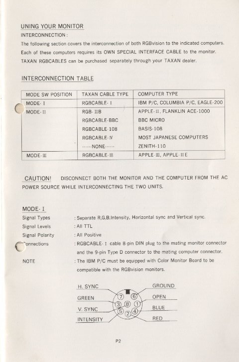
Using the TTL input (8 pin DIN plug): connect the BBC's sync (=composite sync) to the HSYNC/COMPOSITE SYNC, 0V to ground, R/G/B to R/G/B, and 0V to I/XRGB8 (intensity).
   BBC: 6 pin DIN             monitor: 8 pin DIN
   ---                        ------------------
   0 V      (5) ------------- (6,5) ground, intensity
   red      (1) ------------- (2) red input
   green    (2) ------------- (3) green input
   blue     (3) ------------- (4) blue input
   sync     (4) ------------- (7) horizontal sync/composite sync
   5 V      (6) X
                            X (8) vertical sync
Using the TTL/linear input (EIAJ plug): connect the BBC's sync (=composite sync) to the HSYNC/COMPOSITE SYNC, 0V to ground, R/G/B to R/G/B.
     4 3 2   1
   +-----------+
   | o o o   o |
   |           |
   | o o o   o |
   +-----------+
     8 7 6   5
Pin numbers seen from the inside of the plug.
   BBC (6 pin DIN)            EIAJ, monitor
   ---                        --
   0 V      (5) ------------- ground (5,6)
   red      (1) ------------- red input (2)
   green    (2) ------------- green input (3)
   blue     (3) ------------- blue input (4)
   sync     (4) ------------- Horizontal sync/composite sync (composite) (7)
                            x Vertical sync (8)
   5 V      (6) -------------
                            x Unused (1)
Does anyone have the connection details? (voltage levels/pinouts for TTL & analog RGB modes)
Pin numbers on the connectors are in brackets. The pin numbers are printed on the plugs (not always on the SCART plug though).
Scart connector:
  +------------------------------------+
   \  20                           2   |
    \  |  |  |  |  |  |  |  |  |  |    |
     \                                 | 21
      |                                |
      |  |  |  |  |  |  |  |  |  |  |  |
      | 19                           1 |
      +--------------------------------+
21 = shielding
   BBC                        SCART
   ---                        --
   0 V      (5) ------------- ground (blue), ground (green), ground (red),
                              ground (blanking), ground (RGB switching control)
                              (5,9,13,14,18)
   red      (1) -- Rrgb ----- red input (15)
   green    (2) -- Rrgb ----- green input (11)
   blue     (3) -- Rrgb ----- blue input (7)
   sync     (4) -- 330 ohm -- video input (composite) (20)
   5 V      (6) -- 82 ohm --- RGB switching control (16)
Rrgb is e.g. 330 ohm.
Notes:
On the SCART side, the above inputs always have 75 ohm impedance. This means one can easily lower voltage outputs to those required by the SCART device by placing a resistor before the SCART input, thus creating a voltage divider.
The BBC computer outputs are:
   R,G,B:                 TTL (ca. 3.6V for 'on'), with 68 Ohm impedance.
   sync:                  >= 4V (direct output from a 74LS86 IC)
SCART input ranges are:
   R,G,B:                 0 - 0.7 V
   video input:           0 - 1 V
   RGB switching control: high (1-3V) for RGB, low (0-0.4V) for composite
We want to use the BBC's (TTL) RGB signals, so 'RGB switching control' should get in the range of 1-3 V. We can use the 5V signal from the BBC for this, using a resistor of say 82 Ohm to give ca. 2.5 V.
Measuring, I found the sync signal from the BBC is more than 4 V eff. (and the peak?); 330 Ohm is large enough to reduce it to less than 1 V (a much larger resistor also works fine). However, a discussion on the BBC-mailing list reminded me of the fact that the BBC's sync output is actually meant for a high impedance monitor input. This means there's a problem as 74LS ICs can only deliver about .4 mA for the 1 state. Expect further updates, but note also that the cabling above does work for me and others.
The RGB output from the BBC is TTL (0 V is off, >=3.5 V is on; the actual value in this case is around 3.6V (with nearly square outputs IIRC, see below for comments on eff/peak) which we can reduce using resistors of at least ca. 330 Ohm. Note: In old SCART docs the voltage is 1 V, and I was told that the newer .7V was simply due to redefinition of peak to effective value. One of the problems here is that the SCART docs are not freely available and sources on the web do not all say the same thing... The voltage level is said to be 0.7V peak-to-peak in other documents. So, who's right? Expect further updates here too, and again note that 330 Ohm is perfectly in order and used by many people. It's just the lower limit that might change.
(The lower limit for Rrgb:
3.6V/0.7V=5.14, so total resistance should be 4.14*75=311 Ohm at the
very minimum; minus the 68 Ohm for the outputs gives a Rrgb of 243
Ohm. However, this gives the maximum intensity for the computer
image, which is almost certainly not what you want and you'll have
to turn down the brightness each time you use the computer on the
TV)
The resistors are best placed inside the SCART connector where there's plenty of room for them.
NOTE: Some people suggest using voltage level converter ICs to get around any reflections that occur at the places where resistance changes. I've used the simple method on various BBCs and various TVs without seeing any of the effects of reflections like ghosting/blurred pixels. So I would not bother with it. If your TV set gives problems, you may want to try using a voltage level converter IC.
| To email me, go to this page |
Last modified: Thu Nov 1 23:48:01 CET 2012